Most commercial HVAC systems utilize a ceiling plenum for air movement, locating HVAC equipment, and concealing building features such as control wiring, piping, electrical conduit, structural members, and more. Ceiling plenums are often used as a route for return air to make its way back to the central air handling unit (AHU) by allowing air to flow freely through. Where more control is required, return air may be directly ducted through the plenum to the AHU, making the air in the plenum mostly stagnant. Floor plenums are now becoming more common in commercial HVAC systems in the form of underfloor air distribution (UFAD) systems. Regardless of the type of plenum space used in a building, assigning loads to the plenum can play an important role in sizing terminal units, supply fans, and terminal and central cooling coils.
Plenum loads are influenced by three main sources:
Additional sources may exist depending on the specific characteristics of the space. For example, with a UFAD system, floor-mounted appliances may cause heat transfer into the floor plenum.
The primary difference in system performance between traditional ceiling plenums and UFAD systems is that in ceiling plenums, the cooling load is added to the return air, whereas in UFAD systems, it is added to the supply air. This will impact the required inlet and outlet temperature and humidity when selecting your central AHU.
The diagram below shows how the cooling load from a UFAD plenum enters the space.

The diagram shows that the load from the plenum of a particular space remains confined to that space until the air is conditioned again by the AHU. The additional load introduced between the AHU outlet and the supply terminal means that the leaving temperature from the coil must be adjusted to ensure the proper supply temperature is met for air entering the space.
With ceiling returns, the plenum load is added to the air on the return side. This means that it will not affect the supply air temperature or the supply airflow rate. The figure below shows how the plenum load contributes to the system in a ceiling return.

If the plenum load for a space is added to the space load, airflow calculations will be higher than necessary. In addition to lower efficiency of the system, this can cause issues in sizing other spaces. For example, if the system were a constant air volume (CAV) single-zone system, then outdoor air for the building would be driven by the space with the highest percentage of outdoor air. By assuming the plenum load is part of the space load, each zone’s airflow will be overestimated, leading to over-ventilation and excess energy usage year-round.
One way to think of this is that the plenum load is shared by all spaces and is experienced at the AHU inlet; it is not just added to the space that the plenum serves. Instead of impacting the supply airflow volume or conditions, the load is being added to the return side of the AHU and will impact coil selection.
The effects of the plenum load in a ducted return system are almost identical to that of an unducted system. However, since the return air is contained in ducts, the plenum is at risk of becoming very warm in the summer and cold in the winter. Typically, the return ductwork is under negative pressure relative to the plenum, causing plenum air to leak into the return ductwork. Consequently, the plenum load is generally absorbed by the return air, behaving similarly to an unducted return. For this reason, the plenum load will generally be absorbed by the return air and act like an unducted system.
However, if air leakage into the return ductwork is slow, the plenum temperature can still fluctuate enough to impact space comfort. For example, if the plenum becomes overly cold in the winter, it may give a radiant cooling effect in the space. If the supply ductwork were not insulated all the way to the diffusers, then the supply air may be heated or cooled undesirably before reaching the diffuser.
When using your load calculation software, it is important to account for the portion of the plenum load absorbed by walls, roofs, and lights.
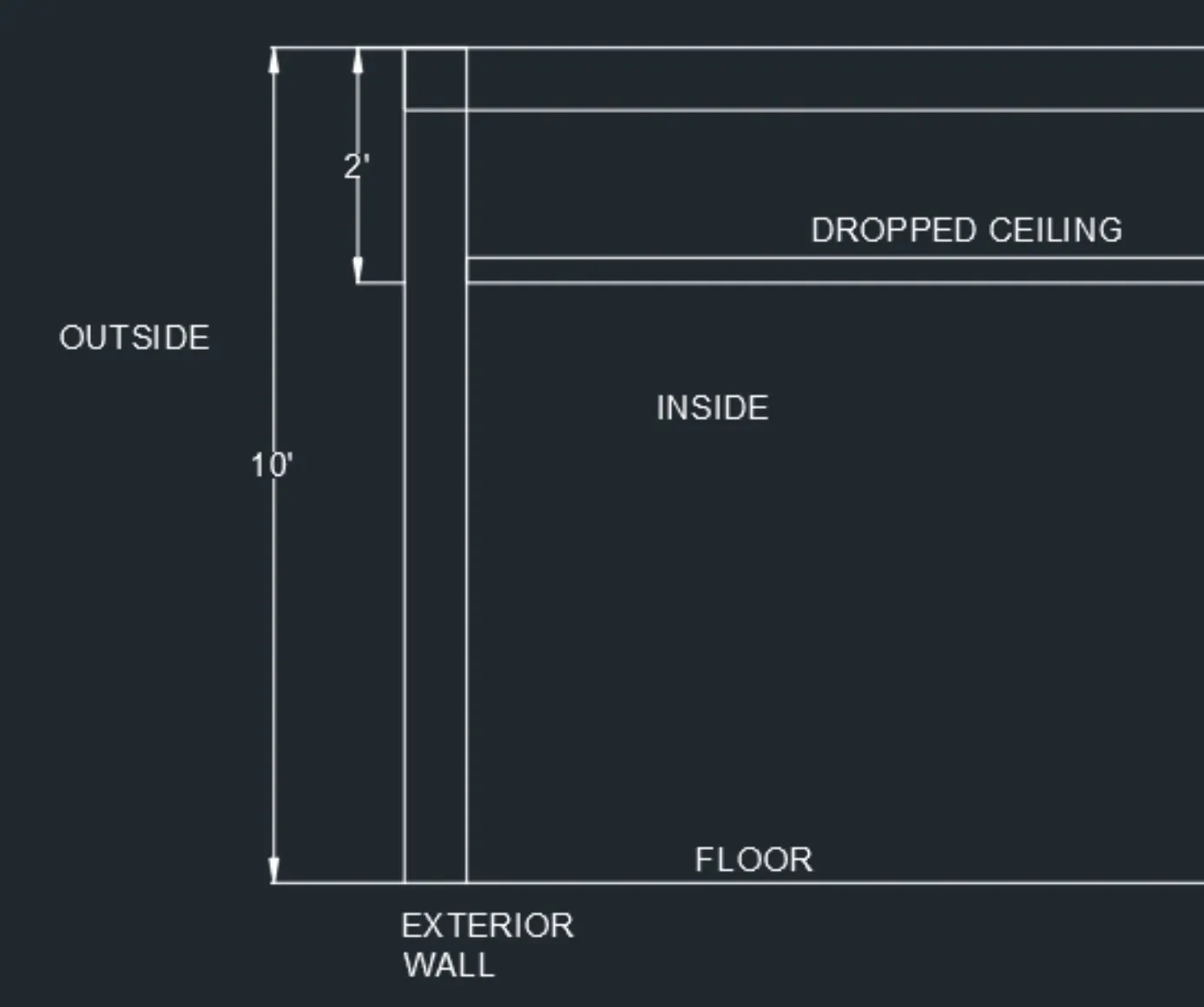
The portion absorbed by the walls can be estimated as the percentage of the wall that is adjacent to the plenum, as shown in the diagram below.

In the case above, the exterior wall is 10’ in height, but the plenum takes up 2’ of that height, so the space ceiling is only 8’ high. To properly account for the wall load, the entire height should be accounted for when entering the wall area. When prompted for the portion that is absorbed by the plenum, 20% would be the proper estimate here, since 2’/10’ (20%) of the wall area is adjacent to the plenum, and since the wall construction is uniform throughout its entire height.
Estimating the portion of the roof load absorbed by the ceiling plenum is more difficult because, in most spaces with ceiling plenums, the entire roof area of the space is adjacent to the plenum. Some designers treat the ceiling plenum like an air gap in the roof assembly, increasing the R-value. However, that will lead to errors in the results since, in reality, part of the load is being added to the return side of the AHU and not directly to the space. Whether the plenum uses an unducted or ducted return will also have an impact on how much of the roof load is absorbed by the plenum.
One way to estimate would be to assume that the convective portion of the roof load is added to the plenum, while the radiative load goes directly to the space. Although this method is not tested, it can be used as an initial estimate for your calculations. ASHRAE recommends a 60% radiative and 40% convective split from roof loads. Common estimates for the load absorbed by the plenum are usually around 30%, however it is up to the designer to make this decision.
Remember that regardless of the fraction of roof load transferred to the plenum, the space load from the ceiling will still need to be split into radiative and convective portions.
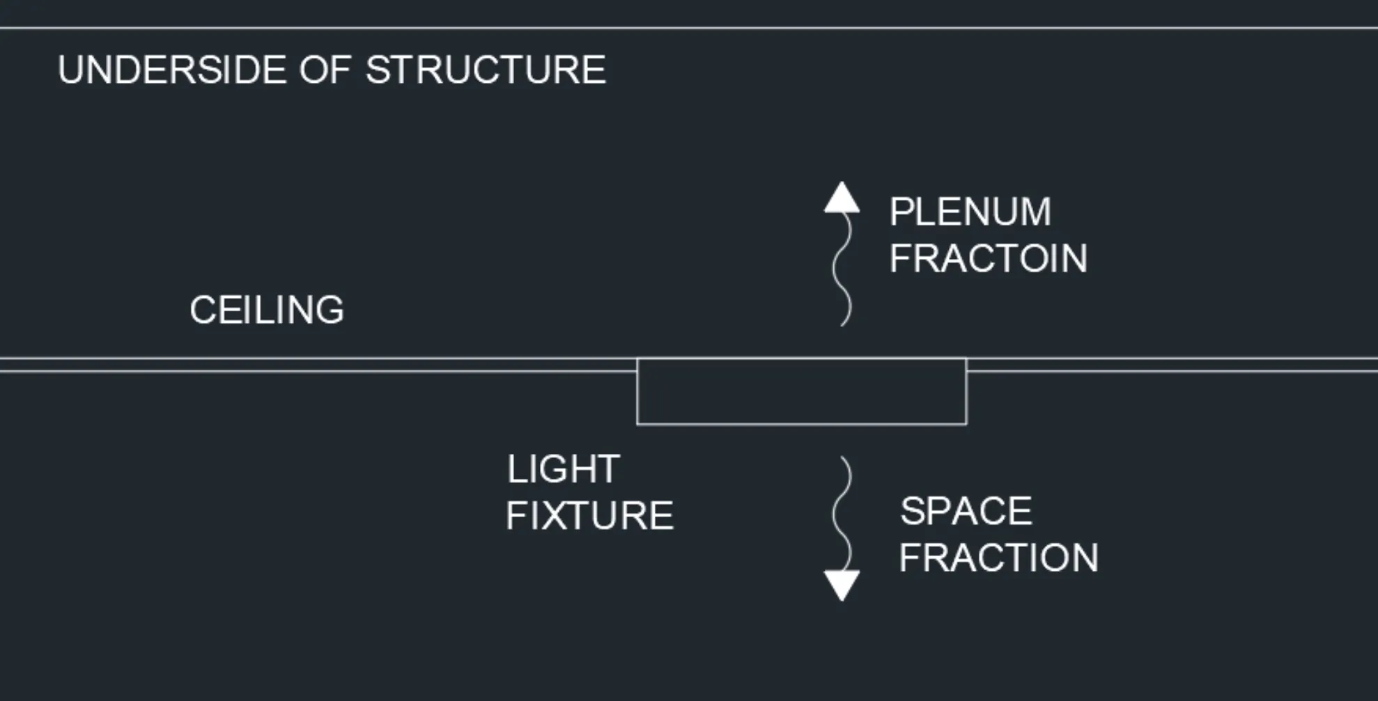
The amount of heat from lighting that transfers into the plenum is dependent on several factors, including the type of light, ballast, proximity to diffusers/return grilles, and air velocity. ASHRAE has published estimated values for the percentage of heat from lights that goes straight into the plenum without ever entering the space. These estimates are found in the 2021 Fundamentals Handbook and range anywhere from 0% to 88% of the heat from the light.

Due to the wide range of values, it is important to attempt to make a proper estimate of this value. This is especially important because the fraction of heat entering the space from lights can be highly dependent on airflow velocity, and the total space load will then dictate the total airflow required from the diffusers, making these variables co-dependent.
Since lighting is handled by the electrical designer, it is important to coordinate diffuser locations with light locations. If these layouts are not coordinated and specified within the reflected ceiling plan (RCP), the contractor may install them differently than what was expected, altering the space and plenum fractions of the lighting load and affecting thermal comfort.
Plenum loads are simply an adjustment of where heat gain takes place within a system. By ignoring the bypass effect that plenums can create, the heat gain will still be added to a space, however, the way in which it is accounted for will be different. This can cause miscalculations in both the peak load and timing of the peak load, leading to the oversizing of zone terminal units and potentially incorrect sizing of the central AHU coil and supply fan. Properly accounting for and anticipating the impacts of a ceiling plenum requires coordination with the electrical designer, mechanical and electrical contractors, and the architect.
HeatWise allows users to account for plenum loads on a space-by-space basis by allowing:
The HeatWise QuickHelp feature can help walk you through these inputs and give you recommendations on what values to use.